
Whether it’s a home or a busy office, having a heating and cooling system helps to keep any space pleasant. A skillfully created HVAC plan guarantees that interior areas remain comfortable, secure, and energy-efficient.
One of the first things one does while building or renovating is to generate a decent HVAC strategy. An HVAC layout locates and directs the arrangement of heating, cooling, and various types of ventilation systems.
This blog will help you to understand what an HVAC system is, why it’s vital, how to interpret one, and how to design one suited to your building’s requirements.
What is the HVAC plan
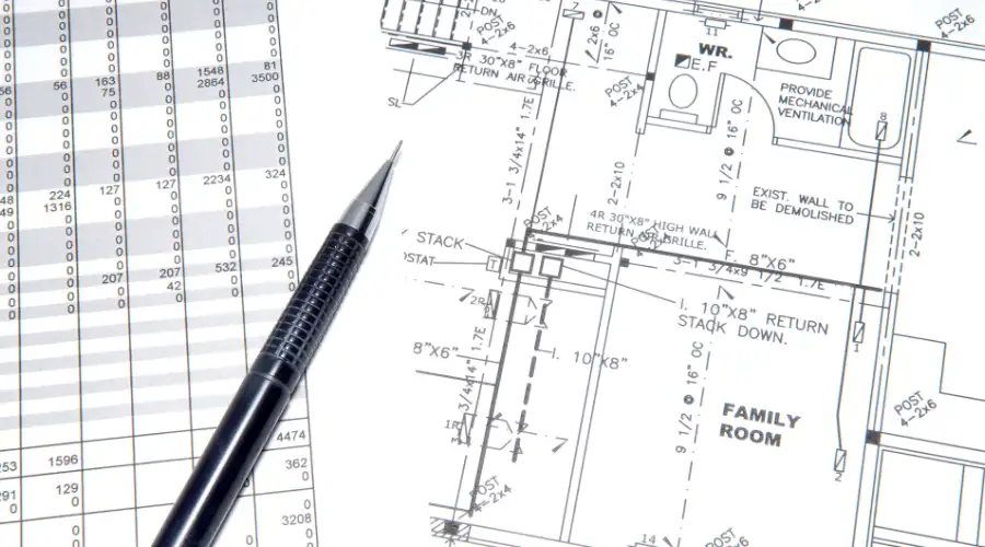
An HVAC is a detailed drawing that shows how heating, ventilation, and air conditioning will be arranged in a building. An HVAC plan can be a flat drawing (2D) or a more detailed 3D drawing that shows how heating and cooling systems will be installed. This plan is created by a trained engineer and includes all the necessary parts and their arrangement. It helps to plan, set up, and maintain the system safely and easily.
Importance and Purpose of the HVAC Plan
When constructing a new building or renovating an existing one, maintaining a comfortable and clean indoor environment is essential. HVAC drawings serve as a guide for the appropriate placement of heating and cooling systems.
HVAC plans help avoid mistakes and save time, making it easier to rectify issues as they arise. They also verify whether the system adheres to energy rules and regulations, ensuring safety. A good drawing helps in planning air movement, reduces waste, and adheres to standards.
Benefits of the HVAC Plan
HVAC floor plans outline the comprehensive design for heating, cooling, and air circulation within a building. They can be useful in so many ways:
- Easy Fix: If a proper HVAC plan is in place for the building, it is easier to address problems later. All the wires, machines, and parts are labelled. This helps you easily find and repair issues without incurring any additional costs.
- System Installation: These plans are the master guide for installing HVAC systems. From purchasing the equipment to installing it in the correct location, everything is done according to the plan.
- Cost Planning: HVAC plans help determine the cost of the system, allowing for more accurate budgeting and avoiding unexpected expenses later on.
Types of HVAC Drawings
When planning or installing an HVAC system, different types of drawings help professionals understand how everything fits and works together. Each type of drawing serves a specific purpose and provides a different view of the system.
1. Schematic Drawings
A schematic depicts a fundamental diagram of the functioning of the HVAC system. Rather than on dimensions or precise placement, these sketches centre on how energy moves through the system and how the air travels. It has a Handling Unit (AHU) with air handlers, coils, valves, sensors, and fans. Schematic illustrations enable engineers and architects to grasp the general design and operation of the system.
2. Plan Drawing
Plan drawings give a top-down view of the HVAC systems. This 2D layout shows where equipment, vents, HVAC ductwork, and parts are placed within the buildings. These drawings are made to scale, meaning they match real-life sizes, and they help everyone understand how the HVAC parts fit into the space alongside the builder’s design.
3. Elevation Drawings
Elevation drawing shows the system from different angles, such as the front, side, or back. They help explain the height, position, and direction of HVAC parts in relation to the builder’s structure. These drawings make sure that HVAC equipment doesn’t interface with walls, beams, or other systems.
4. Isometric Drawings
Isometric drawings give a three-dimensional perspective of the HVAC system on a level plane. These drawings illustrate how components are spatially arranged to further clarify the system’s structure. Usually drew items at a 30-degree angle for a realistic appearance. For more complex systems with numerous components that require thorough preparation, this type of drawing is particularly helpful.
How to Read an HVAC Plan
For anyone working in construction design or construction, reading an HVAC plan is an essential ability. To guarantee the correct installation, performance, and upkeep of the system, architects, designers, and contractors all need to understand these drawings. These are some instructions to get you started:
1. Understanding Scale and Measurement: HVAC plans are usually drawn to scale, which means the size of the drawing matches real-life measurements, just in a smaller format.
2. Interpreting Symbols and Legends: HVAC drawings utilise specialised symbols and legends to illustrate system components. These symbols represent things like fans, air vents, ducts, valves, thermostats, and more. Such indications include:
- Colour Coding
- Arrows and Direction Signs
- Material and Equipment Codes
3. Reading Dimensions and Annotations: HVAC drawings also include dimensions such as numbers and arrows, that indicate the size and location of each part. Annotations are short notes that explain what something is or how it should be installed.
4. Common HVAC Abbreviations: HVAC blueprints often include short forms or abbreviations. Knowing these makes it easier to follow the plan. Some of the most common include,
- CFM: Cubic Feet per Minute (airflow rate)
- BTU: British Thermal Unit(heat energy)
- VAV: Variable Air Volume
- AHU: Air Handling Unit
- D: Duct
- RTU: Rooftop Unit
Recognising these abbreviations helps teams work better together and avoid misunderstandings during installation.
How to Create a House HVAC Plan
Gather Project Information
Start by collecting all the necessary details for planning, such as project requirements. Use architectural and structural plan drawings to understand the layout of the house, along with the model numbers and performance details.
Draw Layouts and Schematics
Once the basic information is received, begin the design process, from creating a floor plan of the house to scale, showing each room and space. Then, design HVAC layouts that show where to place ducts, pipes, vents, and equipment, such as AC units and furnaces.
Label and Annotate
Label every HVAC component, like air diffusers, ducts, pipes, and control panels, and simplify your drawings so that they are simple to read. Include notes, symbols, and a legend that clarify the significance of each item on the drawings, along with dimensions and equipment sizes.
Review and Quality Check
Reading your plan and doing a double check is preferred before your submission. Ensure that the system complies with local building codes and standards. Verify all technical calculations related to heating, cooling, and airflow are accurate.
Finalise Documentation and Sharing
Once your HVAC strategy is complete, prepare the final edition in a tidy and professional style. Send the document to everyone engaged with the project, including the architect, contractor, and HVAC contractor.
Conclusion
Every structure must have an HVAC system to be pleasant, safe, and energy-efficient. It prevents installation mistakes by pointing out the correct layout for heating, cooling, and mechanical ventilation systems. Homeowners and builders who have clear drawings and knowledge of the design save time, energy, and money. Clear HVAC planning helps everything to be simpler and more successful when remodelling or constructing anew. It’s a wise move for any project.