Reinforced concrete beams are important components of almost every new building. By pairing solid concrete with steel, these components form a tough framework. Because they combine strength with problem-solving, builders count on reinforced beams for nearly every job. They can carry weight from floors, ceilings, and walls straight down to columns and pads. With time, this technology has kept advancing. High-strength mixes, corrosion-proof rods, and smart software now squeeze out wastage while boosting safety. As a result, today’s reinforced beams deliver hard-to-beat value. They resist fire, last for decades, and ask modest money for the services offered.
Components and Materials
Concrete Mix Components
Portland slag cement serves as the primary binding agent. It undergoes hydration reactions with water to form hardened concrete. This chemical process creates calcium silicate hydrate gel, providing strength and durability. Fine aggregates (sand) range from 0.15mm to 4.75mm in size. They fill voids between larger particles and improve workability. Quality sand contributes to smooth finishing and overall beam performance.
Coarse aggregates (crushed stone) range from 4.75mm to 37.5mm. They provide a structural backbone and carry compressive loads. Proper natural aggregate selection influences strength and elastic properties.
Water serves dual purposes. It participates in cement hydration and provides workability during placement. The water-cement ratio critically affects final strength.
| Component | Size Range | Primary Function |
| Portland Cement | Fine powder | Binding agent |
| Fine Aggregate | 0.15-4.75mm | Fill voids, workability |
| Coarse Aggregate | 4.75-37.5mm | Structural backbone |
| Water | – | Hydration, workability |
Chemical admixtures enhance specific properties,
- Plasticisers- Improve workability without extra water
- Superplasticisers- Allow significant water reduction
- Air-entraining agents- Create freeze-thaw resistance
- Retarders- Slow setting in hot weather
Steel Reinforcement Essentials
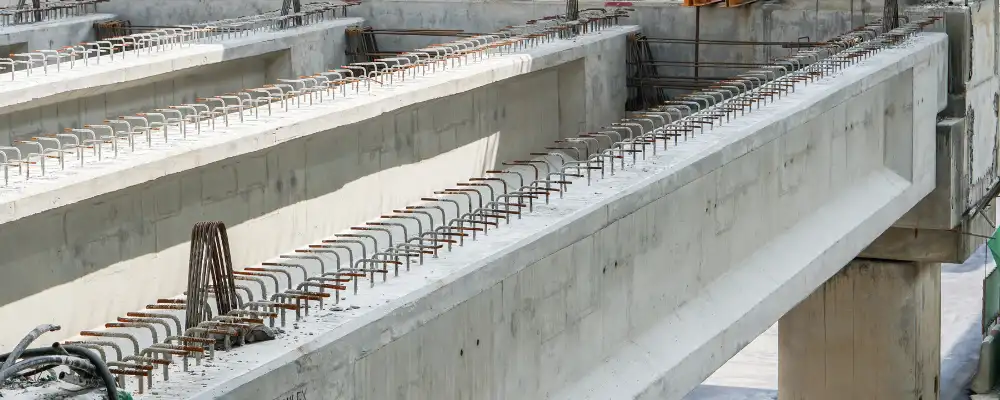
Reinforcing bars (rebars) provide tensile strength. Deformed bars feature surface ribs that create a mechanical bond with concrete. This bond ensures composite action between materials.
| Reinforcement Type | Location | Primary Function |
| Longitudinal bars | Bottom/top of beam | Resist bending moments |
| Stirrups | Vertical spacing | Resist shear forces |
| Ties | Around bars | Prevent buckling |
Primary reinforcement resists bending moments and is placed where tensile stresses develop. Proper placement ensures adequate flexural capacity. Transverse reinforcement includes stirrups and ties. They provide shear resistance and confine longitudinal bars. Spacing varies based on shear force requirements.
Types of Reinforced Concrete Beams
Simply Supported Beams
Simply supported beams rest on two supports. Ends can rotate but cannot move vertically. This creates predictable structural behavior, allowing for efficient load distribution. The beam experiences bending at the midspan when a load is applied, with shear forces concentrated near the supports. The predictable nature of simply supported beams makes them ideal for various structural applications, as they are easy to design and analyze.
Characteristics:
- Maximum moment at mid-span
- Zero moment at supports
- Primary reinforcement is in the bottom
- Straightforward analysis
Advantages:
- Simple design and construction
- Predictable behavior
- Cost-effective for standard spans
- Reduced settlement sensitivity
Typical Applications:
- Residential construction
- Simple span bridges
- Warehouse structures
- Standard building frames
Continuous Beams
Continuous beams span multiple supports, providing efficient load distribution and enhancing structural stability. They reduce material usage while improving performance, making them ideal for large structures, minimising deflections, and withstanding dynamic and static loads.
Key Features:
- Negative moments over support
- Positive moments in spans
- Moment redistribution capability
- Enhanced structural efficiency
Benefits:
- Reduced maximum moments
- Material efficiency
- Structural redundancy
- Better load distribution
Cantilever Beams
Continuous beams are supported at multiple points, unlike cantilever beams, which are fixed at one end. They distribute loads and moments across a single support, reducing maximum bending moments and enhancing stability and load-bearing efficiency.
Design Considerations:
- Maximum moment at fixed support
- Top reinforcement required
- Deflection control critical
- Robust connection details needed
Common Uses:
- Building overhangs
- Balconies
- Parking garage ramps
- Architectural features
| Beam Type | Moment Pattern | Reinforcement Location |
| Simply Supported | Positive only | Bottom only |
| Continuous | Positive and negative | Bottom and top |
| Cantilever | Negative only | Top only |
T-Beams and L-Beams
T-beams combine rectangular webs with flanged tops, providing extra compression area for better bending resistance. Commonly used in reinforced concrete structures, they enhance strength and stability. L-beams, with a right-angle cross-section, are used in structures requiring efficient load distribution.
T-Beam Advantages:
- Increased flexural capacity
- Efficient material usage
- Integration with floor slabs
- Reduced beam depth requirements
L-Beam Applications:
- Edge beams in floor systems
- Spandrel beam construction
- Architectural edge details
- Torsion-resistant members
Applications of Reinforced Concrete Beams
Residential Construction
Grade beams transfer foundation loads to footings. They provide continuous load paths and accommodate soil variations. Floor beams support concrete slabs. Design must balance structural needs with architectural requirements.
Key Considerations:
- Standard residential loads
- Cost-effectiveness
- Utility integration
- Construction simplicity
Commercial Buildings
Office buildings require long-span beams. These often use high-strength materials or post-tensioning. Retail structures need flexible space planning. Beams must accommodate varying load patterns.
Design Factors:
- Heavy live loads
- Long spans
- Vibration control
- Fire resistance requirements
Industrial Facilities
Manufacturing buildings support heavy equipment. Here, dynamic loads and vibrations require special consideration. Warehouse structures carry high storage loads and beam design must accommodate forklift operations and racking systems.
Special Requirements:
- Equipment load concentrations
- Dynamic force effects
- Chemical exposure resistance
- Maintenance accessibility
Infrastructure Projects
Bridge beams resist complex load combinations. Vehicle loads, impact effects, and environmental actions govern design. Highway structures require high durability. Exposure to salts and weather cycles affects material selection.
Performance Criteria:
- Extended service life
- Minimal maintenance
- High load capacity
- Environmental resistance
| Application | Typical Span | Key Design Factor |
| Residential | 3-8 meters | Cost efficiency |
| Commercial | 6-15 meters | Long spans |
| Industrial | 8-25 meters | Heavy loads |
| Infrastructure | 10-40 meters | Durability |
Design Considerations
Load Analysis
Buildings experience different types of loads. Dead loads include permanent structural elements. Self-weight, walls, roofing, and fixed equipment contribute to dead loads. Live loads represent occupancy and use patterns. Building codes specify minimum values for different occupancy types. Environmental loads include wind, seismic, and temperature effects. Location and exposure conditions determine these loads.
Flexural Design Process
Beam analysis assumes plane sections remain plane. This allows strain distribution calculations across the cross-section. Under-reinforced beams fail by steel yielding first. This provides ductile behavior with adequate warning. Over-reinforced beams fail by concrete crushing. This creates brittle failure that must be avoided.
Shear Design Requirements
Shear failures occur suddenly without warning. Proper shear design prevents catastrophic collapse. Concrete provides base shear resistance. Transverse reinforcement adds additional capacity. Deflection limits ensure user comfort. Excessive deflection can cause cracking in non-structural elements.
Detailing and Reinforcement Layout
Development Length
Development length ensures bars reach full strength. Inadequate development causes bond failure. Factors Affecting Development Length,
- Bar size and type
- Concrete strength
- Cover thickness
- Bar spacing
- Transverse reinforcement
As per the Indian Standards code IS 456:2000:
Standard Development Length: Ld = Øσs / 4⋅τbd
Where Ø = nominal diameter of reinforcement bar
σs = Stress in bar at the section considered at design load
τbd= Design bond stress
Bar Spacing Requirements
Minimum spacing ensures proper concrete placement. Bars must be spaced for aggregate size and vibration access. Minimum Clear Spacing,
- 1 inch minimum
- Bar diameter
- 4/3 × maximum aggregate size
Maximum spacing controls crack distribution. Closer spacing promotes better crack control.
Concrete Cover
Cover is the gap left for concrete to be poured between steel reinforcement and the edge of the beam. It protects reinforcement from corrosion. Greater cover increases durability but reduces effective depth. As per the IS 456:2000, a minimum cover of 25mm must be left for beams.
Construction of Reinforced Concrete Beams
Formwork Systems
Timber formwork offers flexibility and low cost and is suitable for small projects and custom shapes. Engineered systems provide accuracy and efficiency. Steel or aluminum components ensure dimensional control.
Formwork Design Loads must consider:
- Fresh concrete pressure
- Construction live loads
- Wind loads during placement
- Equipment loads
Reinforcement Placement
Accurate placement ensures design performance. Reinforcement schedules guide field installation. Support systems maintain bar position. Chairs, bolsters, and spacers prevent displacement during concrete placement.
Quality Control Checks:
- Bar size verification
- Spacing measurements
- Cover dimension checks
- Lap splice lengths
Concrete Placement
Proper placement prevents segregation and ensures quality. Workability must suit reinforcement congestion. Consolidation removes air voids, while vibration ensures complete concrete encasement of reinforcement.
Placement Guidelines:
- Avoid free fall over 5 feet
- Place in horizontal layers
- Vibrate systematically
- Avoid over-vibration
Curing Procedures
Proper curing ensures development of full strength. Moisture and temperature control are essential.
Curing Methods:
- Water curing (ponding, spraying)
- Membrane compounds
- Steam curing
- Insulated blankets
Curing Duration:
- Normal cement: 14 days minimum
- High early strength: 7 days minimum
- Cold weather: Extended periods
Conclusion
Reinforced concrete beams form the core of almost every modern building. By pairing strong concrete with resilient steel, they form low-cost, long-lasting supports that meet many needs. Building these beams well requires solid know-how of materials, structural design, and job-site methods. Trustworthy performance comes only when each piece of that puzzle works as it should. Real command of this craft grows over years of reading, measuring, and adjusting forms. Work done with patience and care lets a beam guard people and property for decades.