
Knowing how the soil reacts under load is central to constructing safe buildings. A Plate Load Test (PLT) helps engineers determine the maximum load the ground can support and the extent of soil settlement that may occur. By forcing a steel plate into the ground and measuring the movement, the test provides tangible and accurate information. It is best applied to shallow foundations and assists in validating previous reports on the soil. Because it is easy to implement and inexpensive, most construction teams rely on it for on-the-spot site analysis.
If you need professional assistance in soil testing, foundation design, or overall construction services, Brick & Bolt can assist you. We merge technical knowledge with practical experience to ensure that your project begins on solid ground—literally. Contact Brick & Bolt for durable, quality construction.
What is a Plate Load Test?
The Plate Load Test is done directly on-site to find out how much load the soil can safely carry and how much it may settle under pressure. A steel frame having a rigid foundation is loaded incrementally. The corresponding settlements are measured for each increment of load.
This provides information about the soil behaviour under real conditions of loading. This data is especially useful in the design of shallow foundations and is widely utilized in cohesive soils and non-cohesive soils. Immediate results are generated for it, facilitating rapid decision-making during the construction process.
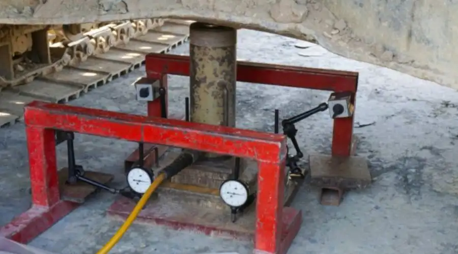
How Does a Plate Load Test Work
The test requires loading a steel plate, preferably 300 mm to 750 mm in size, onto the prepared ground surface at the specified foundation level. The plate is subjected to load increments by a hydraulic jack, and its consequential settlements are determined with dial gauges.
Each load increment is sustained for a particular time, and settlements are monitored at frequent intervals. The testing is repeated until a pre-settlement is achieved or the soil collapses. The load-settlement results so achieved are used to determine the bearing capacity of soil and settlement behaviour of the soil under structural loads.
Benefits of Plate Load Test
The plate load test has numerous advantages:
- Direct Measurement: It gives instantaneous readings of soil bearing capacity and settlement.
- Simplicity: The testing arrangement and procedure are simple, with minimal equipment.
- Cost-Effective: This minimizes the requirement for intensive laboratory testing.
- Versatility: It can be used in different types of soil, such as sand and clayey soils.
- Immediate Results: It allows for prompt on-site decision-making.
All these advantages make the plate load test a wonderful asset in geotechnical explorations, providing a safe and economic foundation design.
Limitations of the Plate Load Test
Although it has its merits, the plate load test has some limitations:
- Depth Limitation: The test evaluates soil behaviour at shallow depths only, making it unsuitable for deep foundations.
- Time-Consuming for Cohesive Soils: In cohesive soils, loading must be maintained longer to account for consolidation, making the test time-intensive.
- Equipment Sensitivity: High-quality results are based on careful equipment calibration and operation.
- Soil Disturbance: Test excavation may interfere with the natural soil structure.
- Area Representation: The test gives data for a small area, which might not be representative of the whole site conditions.
It is essential to understand these limitations in order to accurately interpret test results and make informed design decisions.
Plate Load Test Apparatus
In order to conduct a plate load test correctly, the following equipment and materials are required:
- Steel Plate – A rigid steel plate (usually 300–750 mm diameter and 25–50 mm thick) used to apply load on the soil surface.
- Hydraulic Jack and Pump – A jack that forces the plate down into the ground. It needs to be able to handle more than the intended load, typically 1.5 times as strong.
- Steel Shims – Thin metal strips for adjusting or levelling the plate, and at least 6 mm thick.
- Support Beam or Truss – A massive beam used to counteract the upward thrust when the jack forces the plate downwards.
- Dial Gauge – An instrument that measures how far the plate drops into the ground. It must be extremely accurate, to 0.02 mm, with a measuring range of 0–250 mm.
- Pressure Gauge – It shows how much force the hydraulic jack applies during the test.
- Loading Frame – A heavy-duty frame to support the setup. It must be capable of carrying a minimum of 1.5 times the test load and have a provision for the force to be applied at the plate centre.
- Tools for Loading Platform – Comprises tools used in applying weight and keeping it stationary during testing.
- Tape or Measuring Scale – Minimum 3 meters in length to verify distances or movement.
- Tripod, Plumb Bob, and Spirit Level – Employed to verify the vertical and level position of the assembly.
- Hammer – Convenient for making small adjustments while assembling.
- Spanners or Wrenches – Utilized in tightening bolts or fittings.
- Dry Cloth – To clean tools and remove any dust or grease.
Plate Load Test Procedure- Step By Step
1. Excavation and Setup
Start by digging a pit at the test location. The depth should match the actual foundation level, and the width must be at least five times the plate size. In the centre of the pit, make a small, flat hole the same size and thickness as the test plate.
2. Placing the Test Plate
A mild steel plate, usually between 300 mm and 750 mm wide, is placed at the center of the test pit. A column or beam is set above this plate to pass the load down. For square footings, use a square plate; for circular footings, use a round one.
3. Choosing the Loading Method
Use either gravity loading (sandbags on a platform) or hydraulic jacking (load applied slowly through a jack) to apply pressure.
4. Installing Measuring Instruments
Two dial gauges are fixed diagonally on a stable frame to track any movement. These gauges help track settlement without being affected by plate movement.
5. Applying the Load
The test starts by applying a light seating load of 7 T/m², which is then removed before the actual loading begins. Apply loads in small steps and measure settlement regularly. Continue until the plate reaches 1.5 times the expected load or 3 times the design pressure. Record all data carefully.
Equations for Foundation Settlement Calculation from Plate Load Test
Engineers use straightforward formulas based on the plate load test results to estimate how much a foundation settles after construction. The formulas change based on whether the soil is sand or clay.
For Clayey Soil:
To find the foundation settlement in clay soil:
Settlement of foundation = Settlement of plate × (Width of foundation ÷ Size of plate)
This means that the bigger the foundation compared to the test plate, the more the actual foundation might settle.
For Sandy Soil:
For sandy soil, the calculation changes slightly:
Settlement of foundation = Settlement of plate [(Width of Pit × (Size of plate + 0.3) )÷ (Size of plate × (Width of Pit + 0.3)²)]
This formula helps adjust for how sand behaves under pressure, considering both the size of the plate and the actual foundation width. These equations help engineers design safe and stable foundations by predicting how much movement may happen in real soil conditions.
Conclusion
The plate load test is an important geotechnical engineering tool that directly indicates soil bearing capacity and settlement characteristics. Its simple protocol and quick results make it an essential tool for the design of safe and cost-effective foundations. But its limitations must be understood to properly interpret it.