
While planning to construct a house for the first time, many property owners often get confused by architectural plans and are unable to comprehend them. However, they are one of the most important representations of how a house will look and function once constructed. These drawings must be thoroughly understood and analysed to ensure that dream homes are realised as envisioned by the property owners. Therefore, we present a comprehensive guide on architectural plans, including the floor plan meaning, types of a building layout plan and how to interpret them. Read on to learn more.
What are Architectural Plans?
An architectural plan is a two-dimensional representation of the layout and arrangement of spaces in a specific area. It generally depicts a building top view or a floor, site or room as viewed from a certain height (which is commonly the window sill height in architectural floor plans). A plan diagram can be a drawing consisting of several commonly used architectural shapes, symbols and annotations or even just a line drawing (referred to as a line plan). Architectural plans, along with other relevant drawings, guide the construction process and ensure that a project is built as visualised and designed.
Types of Architectural Plans
Architects and other consultants in the construction industry are responsible for preparing several types of architectural plans to ensure the success of a building project. The most notable types are:
Site Plans/ Master Plan
A site plan or master plan is a drawing which represents the entire site in which a construction project is happening. It includes crucial elements like site dimensions, entryways and exits, vehicular and pedestrian paths, landscape elements like water bodies, vegetation and semi-open spaces, and the footprints of all built structures. Such plans are most useful in large-scale projects, where the location, dimensions, type and other relevant details of each built, semi-built and open space are mentioned.
Floor Plans
A floor plan or floor map is one of the most important drawings of any construction project. A typical floor plan depicts the layout of all rooms and spaces across a building floor, with critical details like room sizes, floor levels, positioning of doors, windows and other openings and furniture placement. Special features like double-heights, cut-outs in slabs, skylights, planters and FFL (Finish Floor Level) differences are also mentioned in building floor plans.
Detailed Section Plans
Certain special areas of floor plans, such as bathrooms, skylights, swimming pools and staircases, require details that cannot be specified in the main building floor plans. These are thus highlighted in the base plan and detailed out in other enlarged plans with their unique features. A section plan of building structures is one in which a space is assumed to be cut along a line, and what would be visible in this cut section is depicted in a two-dimensional layout.
Reflected Ceiling Plans (RCP)
Unlike a regular plan which depicts a view from above, Reflected Ceiling Plans (RCPs) are two-dimensional views of ceilings as viewed from below (generally the floor). Detailing out building characteristics like false ceiling patterns, electrical and plumbing conduits along ceilings and beam layouts at slab bottoms, RCPs are significant construction documents. They are commonly prepared by both structural/ civil engineers and architects.
Electrical, HVAC and Plumbing Plans
A building’s operational success is majorly quantified by the efficiency of its services, which include electricity, plumbing and sanitary functions, and HVAC (Heating, Ventilation and Air Conditioners). During construction, these aspects are taken care of with the aid of services plans prepared by architects or services consultants. Electrical plans include the positioning of all fans, lights, switchboards, electrical panels and other related equipment and are utilised mainly before the casting of every concrete floor slab and after the walls are built. Plumbing layouts or plans incorporate the positioning, sizes and types of all sanitary fittings, along with the routing of all supply and discharge pipes. Services plans also contain details of additional building components like solar power systems and rainwater harvesting networks.
Landscape Architecture Plans
A landscape architecture plan—generally designed by a specialist landscape architect/ designer—is a depiction of all the spaces around the actual built structures in a project. This plan includes details of circulation paths, water bodies and semi-open spaces, along with their materials and patterns. The type of vegetation/ plantation to be done in all green spaces and their irrigation systems are also specified. Landscape plans help create usable, functional and aesthetically pleasing spaces in the areas around buildings.
Interior Design Floor Plan
An interior design floor plan details out the positioning, sizes and other relevant details of all elements inside the empty shell of a house. These include furniture such as sofas and dining tables, storage components like wardrobes and kitchen cabinets and light fittings. Although some of these elements are depicted in a typical floor plan, they are only indicative. However, interior design plans include specific details of all of these objects along with general space colours and materials, helping create a cohesive ambience that reflects individual styles and design languages.
Elements of a Building Plan and How to Read a Building Plan Drawing
Architects and other professionals associated with the construction industry across the world use a few commonly accepted symbols and annotations in architectural plans and drawings. These enable the easy understanding and interpretation of the drawings, helping create an efficient process of building construction.

A typical floor plan drawing
Common Annotations Used in Architectural Plans
- W 1/2/3/etc.: Window- may be of any type, i.e., sliding, hinged, top hung, etc.
- SLW: Sliding window
- D 1/2/3/etc.: Door- may be of any type, i.e., sliding, hinged, etc.
- SLD: Sliding door
- MD: Main door
- V 1/2/3/etc.: Ventilator, generally placed in kitchens and bathrooms
- FFL: Finish Floor Level
- C 1/2/3/etc.: Structural columns (generally made of RCC or steel)
- OP: Opening
- UP/ DN: UP/ Down- generally used to denote the direction in which staircases are climbed
- GF plan: Ground floor plan
- FF: First floor
- SF: Second floor
- TF: Third floor
Common Annotations Used in Plumbing Drawings
- WB: Wash basin
- SH: Shower
- WC: Water closet
- HF: Health faucet
- FT: Floor trap
Common Annotations Used in Electrical Drawings
- SB: Switch box/board
- F: Fan
- L: Light, may be of any kind
- CL: Ceiling light
- WL: Wall light

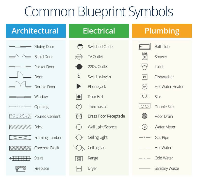
Common symbols used in architectural plans
Image source: Link
However, these are only some of the symbols commonly used in building layout plans and drawings. If any other unconventional symbols/ annotations are used, they are generally mentioned and explained in a separate table or footnote in the same drawing. Check out Brick & Bolt’s curated set of layout plan drawings and floor plan images to gain an insight into how they look. It is advisable to consult architects, structural engineers, project managers, contractors and other professionals of the industry to accurately interpret architectural plans and ensure successful execution of the same.
Getting the Best House Plan Drawing
A simple Google search can often yield results for getting a home plan design online. However, such plans rarely fulfill individual requirements while still remaining functional and beautiful. Brick & Bolt is a leading construction company in India, with a team of expert architects who customise the floor plan design for every project. With over 7000 homes completed with the aid of these building plans with dimensions, the company has secured its reputation as a dominating force in the construction industry. Contact Brick & Bolt today to get floor plans tailored to your needs and begin the construction of your dream home!